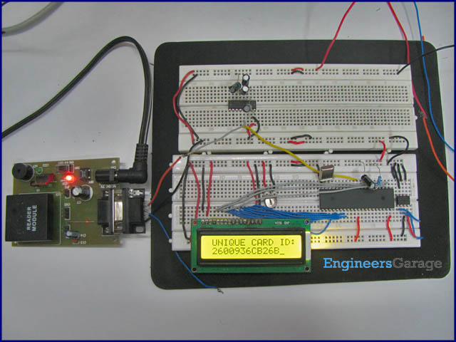
DESCRIBTION:
- An RFID module basically consists of two parts, namely, a tag and a reader. A typical RFID system consists of an antenna, a transceiver and a transponder (RF tag). The radio frequency is read by the transceiver and the information is transferred to a device for further processing. The information (the unique serial number) to be transmitted is stored in the RF tag or transponder.The transponder contains a chip and an antenna mounted on a substrate. The chip transmits the relevant information through antenna. The antenna also receives the electromagnetic waves sent by the RFID reader.Different RFID tags work on different frequencies. Here low frequency, 125 kHz, RFID tags have been used. These tags work within a range of 10 cm. When an RFID tag comes in this range, the reader detects it and sends a unique code of the tag serially. This serial code, consisting of 12 bytes, is received by the microcontroller.
A serial level converter is required for AT89C51 to receive these serial signals. IC MAX232 has been used for this purpose to interface the RFID reader with microcontroller. The circuit connections are as follows:
Receiver1 (R1) of MAX232 has been used for the serial communication. The receiver pin of RFID reader is connected to R1IN (pin13) of MAX232. R1OUT (pin 12) of MAX232 is connected to RxD (P3.0) of microcontroller.RFID ReaderMAX232AT89C51RxR1 INR1 OUTRx
Pins 1-3 of port P1 (P1.0, P1.1 & P1.2 respectively) of AT89C51 are connected to the control pins 4-6 LCD. The unique identification code of RFID tag is displayed on the LCD.
In the program, Timer1 is configured for serial communication. The baud rate is set to 9600bps for data transmission. The LCD is initialized to display the code. When a card/tag comes in the proximity of RFID reader, the microcontroller reads the code and sends it to the LCD module.
//Program to interface RFID with 8051 microcontroller (AT89C51) #include<reg51.h>

unsigned int data_out,command=0x80,temp;

sfr lcd_data_pin=0xA0; //P2 port

sbit rs=P1^0;        //Register select

sbit rw=P1^1;        //Read/Write

sbit en=P1^2;        //Enable pin

unsigned char card_id[12];


void delay(unsigned int count)    //Function to provide delay

{

    int i,j;

     for(i=0;i<count;i++)

     for(j=0;j<1275;j++);

}


void lcd_command(unsigned char comm)   //Lcd command funtion

{

     lcd_data_pin=comm;

     en=1;

     rs=0;

     rw=0;

     delay(1);

     en=0;

}


void lcd_data(unsigned char disp)  //Lcd data function

{

     lcd_data_pin=disp;

     en=1;

     rs=1;

     rw=0;

     delay(1);

     en=0;

}


lcd_string(unsigned char *disp)     //Function to send string

{

     int x;

     for(x=0;disp[x]!=0;x++)

    {

         lcd_data(disp[x]);

    }

}

void lcd_ini()                  //Function to initialize the LCD

{

    lcd_command(0x38);

    delay(5);

    lcd_command(0x0F);

    delay(5);

    lcd_command(0x80);

    delay(5);

}


void recieve()     //Function to recieve data serialy from RS232

{

    unsigned char k;

     for(k=0;k<12;k++)

     {

         while(RI==0);

          card_id[k]=SBUF;

          RI=0;

    }

}


void main()

{

    int l;

    TMOD=0x20;            //Enable Timer 1

    TH1=0XFD;

    SCON=0x50;

    TR1=1;                // Triggering Timer 1

    lcd_ini();

    lcd_command(0x81);        //Place cursor to second position of first line

    lcd_string("UNIQUE CARD ID:");

    delay(200);

    while(1)

    {

         recieve();

         lcd_command(0xC1);        //Place cursor to second position of second line

         for(l=0;l<12;l++)

         {

              lcd_data(card_id[l]);

          }

      }

}

 Facebook
 Twitter
 Google+
 Rss Feed


0 comments:
THANKS FOR UR COMMENT ....